
Mastering Lines in AutoCAD: Essential Drawing Techniques
“`html
When you’re diving into the world of computer-aided design, one of the first and most fundamental skills you’ll pick up is how to draw a line in AutoCAD. It might sound incredibly basic, but don’t let that fool you. The humble line is the bedrock of virtually every drawing, sketch, and complex model you’ll ever create in this powerful software. From architectural blueprints to intricate mechanical parts, everything begins with a line. And while the basic command is straightforward, AutoCAD offers a surprising depth of tools and methods for drawing lines with precision, efficiency, and intelligence.
Think about it: a line isn’t just a line. It can represent an edge, a boundary, a path, a dimension, or even an axis. Knowing how to manipulate these lines, control their properties, and leverage AutoCAD’s various drawing aids will dramatically impact your productivity and the accuracy of your designs. This isn’t just about clicking a button; it’s about understanding the underlying principles that make AutoCAD such a robust design platform. Let’s explore the essential techniques for drawing lines, ensuring you’re not just drawing, but truly designing with purpose.
1. The Basic Line Command (LINE): Your Starting Point
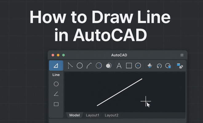
Every journey in AutoCAD begins with the LINE command. It’s the most straightforward way to draw a line, and you’ll find yourself using it constantly. To initiate it, you can simply type ‘L’ or ‘LINE’ into the command line and press Enter, or click the ‘Line’ icon on the ‘Draw’ panel of the Home tab in the ribbon interface. Once activated, AutoCAD will prompt you to specify the first point of your line.
After you’ve clicked or entered coordinates for your first point, the command line will ask for the next point. You can continue clicking points to create a series of connected line segments. If you want to end the sequence, just press Enter or the Spacebar, or right-click and choose ‘Enter’ from the context menu. For a closed shape, you can type ‘C’ for ‘Close’ at the ‘Specify next point’ prompt, and AutoCAD will automatically connect the last point to your first point, creating a polygon. This basic method is perfect for freehand sketching or when you’re not overly concerned with precise lengths and angles initially.
2. Drawing Lines with Specific Lengths and Angles: Precision is Key
While clicking points is fine for quick sketches, professional CAD work demands precision. AutoCAD provides several ways to draw a line with exact lengths and angles. Once you’ve specified your first point using the LINE command, instead of clicking for the second, you can input specific values. For a precise length in a particular direction, simply move your cursor in the desired direction (ensuring Ortho Mode or Polar Tracking is active, which we’ll discuss shortly) and type the desired length, then press Enter.
To draw a line at a specific angle, you’ll use relative polar coordinates. After your first point, you’d type ‘@Length When you need to draw horizontal or vertical lines, Ortho Mode is your best friend. You can toggle it on or off by pressing the F8 key or by clicking the Ortho icon on the status bar at the bottom of the AutoCAD window. With Ortho Mode active, the lines you draw will be constrained to strictly horizontal or vertical orientations relative to your current UCS (User Coordinate System). This feature eliminates the guesswork and the need for angular input when drawing axes, grid lines, or the basic framework of a building plan. It ensures that your lines are perfectly straight, preventing tiny deviations that can accumulate and cause significant problems in larger, more complex drawings. Combine Ortho Mode with direct distance input, and you can quickly lay out precise rectangular forms and orthogonal grids with ease, making the process of how to draw a line in AutoCAD much more efficient for architectural and mechanical drafting. Polar Tracking is like an intelligent compass for your lines. It helps you draw lines at specified angles without constantly inputting the angle value. You activate it by pressing F10 or clicking its icon on the status bar. Once active, you can define a set of common angles (e.g., 0, 45, 90, 135 degrees) in the Polar Tracking settings. (See: Computer-aided design overview.) When you’re drawing a line with Polar Tracking on, as your cursor approaches one of the predefined angles, a dashed green tracking line will appear, indicating that you’re aligned with that angle. You can then simply move your cursor along this tracking line and type in the desired length. This is a huge time-saver for drawing anything with repetitive angular patterns, like spokes on a wheel, roof pitches, or angled features on a machine part, giving you excellent control over how to draw a line in AutoCAD with angular precision. One of the most powerful features in AutoCAD, and absolutely essential for precise drafting, is Object Snap, or OSNAP. Imagine trying to connect a new line precisely to the endpoint of an existing line, or the center of a circle, just by eye. It would be nearly impossible to achieve true accuracy. OSNAP allows you to ‘snap’ your cursor to specific points on existing objects, ensuring perfect connections. You can toggle OSNAP on and off with the F3 key, or by clicking its icon on the status bar. The real power comes from configuring which snap types are active (e.g., Endpoint, Midpoint, Center, Intersection, Perpendicular). When OSNAP is on and you’re near an active snap point, a unique marker will appear (a square for Endpoint, a triangle for Midpoint, a circle for Center, etc.), and your cursor will automatically jump to that exact point. This is critical for creating accurate, connected geometry and forms the backbone of precise drawing in AutoCAD. Without OSNAP, your drawings would quickly become a mess of slightly misaligned lines. Object Snap Tracking, often abbreviated as OTRACK, builds upon the foundation of OSNAP by allowing you to draw lines that are aligned with specific points on other objects, even if those objects aren’t directly at your current cursor position. Think of it as an intelligent projection system. You can activate it with F11 or by clicking its icon on the status bar. With OTRACK active, you can hover over an OSNAP point (like an endpoint or midpoint) and then move your cursor away. A dashed tracking line will appear, projecting horizontally or vertically from that hovered point. This lets you align new points with existing ones without drawing temporary construction lines. For instance, you could start a new line that is precisely aligned vertically with the center of a circle, or horizontally with the endpoint of another line, even if your new line is some distance away. It’s an incredibly efficient way to maintain geometric relationships and ensures your AutoCAD lines are positioned perfectly in relation to other drawing elements. Sometimes, you don’t want to draw a permanent line, but rather a temporary reference line to help with layout or to define a specific orientation. This is where construction lines come in. AutoCAD offers two primary commands for this: XLINE (for ‘construction line’) and RAY. An XLINE creates an infinite line that extends indefinitely in both directions from a specified point. You can draw them horizontally, vertically, at a specific angle, or even offset from existing objects. They’re non-printing by default, making them perfect for setting up grids, finding intersections, or establishing symmetry. RAY, on the other hand, creates a semi-infinite line, starting from a specified point and extending indefinitely in one direction. Both are invaluable for setting up your drawing framework, helping you align objects, and serving as guides before you commit to your final geometry. Learning to use these effectively will streamline how you approach complex layouts and make drawing precise lines much easier. While the LINE command creates individual, separate line segments, the PLINE (Polyline) command creates a single, continuous object made up of multiple segments. Each segment of a polyline is connected to the next, forming a unified entity. This might seem like a small distinction, but it has significant advantages, especially when you’re working with areas, paths, or objects that need to be treated as a single unit. For example, if you draw a rectangle using four separate LINE commands, you have four distinct objects. If you draw the same rectangle using PLINE, you have one single object. This makes selection, editing (like offsetting or changing properties), and area calculations much simpler. Polylines can also have varying widths, making them useful for representing thicker lines, walls, or paths. They can even contain arc segments, offering incredible versatility. When you need a closed boundary for hatching or to calculate an area, a polyline is often the superior choice over a series of individual lines, demonstrating another powerful way to draw a line in AutoCAD. Understanding how to draw a line in AutoCAD with precision is just one piece of the puzzle. To truly master the software, you need to understand how to manage those lines. This means leveraging layers and properties. Layers are like transparent overlays that allow you to organize your drawing content. You might put all your walls on one layer, dimensions on another, and furniture on a third. This makes it easy to turn elements on or off, lock them, or change their visibility, preventing clutter and improving clarity. Each line, whether it’s a simple line segment or part of a polyline, also has properties. These include color, linetype (solid, dashed, hidden), lineweight (thickness), and transparency. By assigning lines to specific layers, you can control these properties globally. For instance, all lines on the ‘Dimensions’ layer might automatically be green, thin, and continuous. You can also override these layer properties for individual objects if needed. This systematic approach to managing your drawing elements is what differentiates a novice user from a skilled professional, ensuring your drawings are not only accurate but also organized and easy to understand. (See: AutoCAD software features and uses.) For those looking to speed up their workflow, Dynamic Input is a feature you’ll want to embrace. When Dynamic Input is active (toggle with F12 or its icon on the status bar), AutoCAD displays a tooltip near your cursor that provides input fields for commands, lengths, and angles. Instead of constantly looking down at the command line, you can keep your focus on your drawing area. This means when you’re using the LINE command, you can type in lengths and angles directly at your cursor, making the process feel more intuitive and direct. It’s a subtle but significant enhancement that can shave off seconds from every command, adding up to considerable time savings over the course of a project. If you’re serious about efficiency when you draw a line in AutoCAD, get comfortable with Dynamic Input. When you’re inputting precise points for your lines, you’ll primarily be using two types of coordinates: absolute and relative. Absolute coordinates refer to points in relation to the origin (0,0,0) of your drawing. So, if you type ‘100,50’ as your first point, AutoCAD places it 100 units along the X-axis and 50 units along the Y-axis from the origin. This is useful for establishing fixed points or global references. Relative coordinates, on the other hand, refer to points in relation to the *last point you specified*. This is where the ‘@’ symbol comes in. If your last point was (100,50) and you input ‘@20,10’, your new point will be 20 units to the right and 10 units up from (100,50), landing at (120,60). For drawing lines with specific lengths and angles, relative coordinates are often more practical, as you’re usually defining segments from an existing point rather than from the absolute origin. Understanding the difference and knowing when to use each is crucial for precision. The ability to accurately draw a line in AutoCAD isn’t just for simple squares and rectangles. It’s the foundation for complex design tasks. Consider drawing a detailed floor plan: each wall, door opening, and window frame begins as a series of lines. For mechanical engineers, every component edge, center line, and dimension line is carefully placed. Architects use lines to define site boundaries, property lines, and intricate facade details. Even civil engineers rely on lines to represent road edges, utility paths, and contour lines on a topographic map. The mastery of these line-drawing techniques allows designers to translate abstract ideas into tangible, measurable, and buildable realities. It’s about more than just digital drafting; it’s about creating a language of lines that communicates design intent clearly and unambiguously. The precision offered by AutoCAD’s line tools minimizes errors and ensures that what is designed on screen can be accurately constructed in the real world. Drawing lines is just the beginning. The real power of AutoCAD comes from your ability to edit and modify them after they’re drawn. You’re rarely going to get everything perfect on the first try, and even if you do, design changes are a constant reality. Knowing how to efficiently manipulate existing lines is just as important as knowing how to create them. The TRIM command lets you cut off portions of lines that extend beyond a boundary. Think of it like using a pair of scissors. You select a cutting edge (another line or object), then select the parts of the lines you want to remove. Its counterpart, EXTEND, does the opposite: it lengthens a line to meet a boundary object. These two commands are fundamental for tidying up corners, creating precise intersections, and ensuring clean geometry, especially when you’re working with multiple intersecting lines for walls or structural elements. When two lines meet at a sharp corner, you often need to smooth it out. FILLET creates a rounded corner (an arc) between two non-parallel lines. You specify a radius, and AutoCAD automatically trims or extends the lines to create the smooth curve. CHAMFER, on the other hand, creates an angled corner (a straight line segment) between two lines. You specify two distances or a distance and an angle. These are crucial for representing rounded edges on mechanical parts, architectural details, or property boundaries where corners are often softened. (See: AutoCAD in engineering applications.) The OFFSET command is a huge time-saver for drawing parallel lines or concentric arcs and circles. You select an existing line or object, specify a distance, and then indicate which side you want the new parallel copy to be created on. This is incredibly useful for drawing walls (offsetting a centerline to create wall thickness), setting back property lines, or creating parallel features in mechanical designs. It dramatically speeds up the creation of repetitive or symmetrical elements. Sometimes you need to split a single line into two separate segments, perhaps to insert a door or window opening. The BREAK command lets you do this, either by picking two points on the line or breaking it at a single point. Conversely, if you have several collinear line segments that you want to treat as a single entity, the JOIN command comes in handy. It merges selected lines, arcs, or polylines that share common endpoints into a single object, simplifying selection and editing. While knowing how to draw a line in AutoCAD is a core skill, professional CAD work also heavily relies on established standards and templates. You wouldn’t want to redefine your layers, linetypes, and dimension styles for every new project. CAD templates (DWT files) are pre-configured drawing files that contain all these settings, ensuring consistency across a project or even an entire organization. A good template will have predefined layers for different object types (e.g., A-WALL, A-DOOR, M-PIPE), standard linetypes (continuous, dashed, center), lineweights, text styles, and dimension styles. When you start a new drawing from a template, all these elements are ready to go, allowing you to focus immediately on drawing your lines and designing, rather than spending time on setup. Adhering to these standards, often based on industry guidelines like ISO or ANSI, is vital for collaboration, maintainability, and clarity of your drawings. It ensures that when someone else opens your file, they understand the meaning and properties of every line you’ve drawn. Even with a solid grasp of the basics, you might run into a few common hiccups when learning how to draw a line in AutoCAD. Don’t worry, these are usually easy to fix! Drawing lines in AutoCAD might seem like a small detail, but it’s where true CAD proficiency begins. By mastering these eight essential techniques – from the basic LINE command to the nuanced use of OSNAP, OTRACK, and Polylines – along with advanced editing tools and an understanding of workflow best practices like templates, you’ll not only draw more accurately but also work more efficiently. Remember, every great design, no matter how complex, is ultimately built from a collection of well-placed, precisely drawn lines. Invest the time in understanding these fundamentals, and you’ll lay a solid foundation for all your future CAD endeavors. “` Trending Now To draw a line in AutoCAD, you can use the LINE command by typing 'L' or 'LINE' in the command line and pressing Enter. Then, specify the first point of your line by clicking in the drawing area or entering coordinates. Continue to specify subsequent points until you're done, and press Enter to finish. The basic command to draw in AutoCAD is the LINE command. You can initiate it by typing 'L' or 'LINE' in the command line, or by selecting the 'Line' icon from the 'Draw' panel in the Home tab. This command is essential for creating lines and shapes in your designs. Yes, you can create closed shapes in AutoCAD by using the LINE command. After drawing the desired line segments, simply connect the last point back to the first point. You can press Enter or right-click and choose 'Enter' to finish the sequence, thus closing the shape. Lines in AutoCAD serve multiple purposes, including representing edges, boundaries, paths, and dimensions in your designs. Mastering line drawing enhances your design accuracy and productivity, making it a fundamental skill for creating detailed and precise models in various fields. To improve your line drawing skills in AutoCAD, practice using the LINE command regularly and explore various drawing aids available in the software. Familiarize yourself with manipulating line properties and utilize shortcuts to streamline your workflow, enhancing both speed and precision in your designs. Agree or disagree? Drop a comment and tell us what you think.3. Ortho Mode (F8): For Perfectly Straight Lines
4. Polar Tracking (F10): Guiding You to Specific Angles
5. Object Snap (OSNAP, F3): Snapping to Existing Geometry
6. Object Snap Tracking (OTRACK, F11): Extending Your Snapping Power
7. Drawing Construction Lines (XLINE & RAY): For Layout and Reference
8. Polylines (PLINE): Connected, Versatile Lines
Beyond the Basics: Leveraging Layers and Properties
Dynamic Input: A Faster Workflow
Relative vs. Absolute Coordinates
Practical Applications: Beyond Basic Shapes
Advanced Line Editing: Refining Your Geometry
Trim and Extend: Cleaning Up Intersections
Fillet and Chamfer: Adding Rounded or Angled Corners
Offset: Creating Parallel Copies
Break and Join: Segmenting and Combining Lines
The Role of Templates and Standards
Troubleshooting Common Line Drawing Issues
Conclusion
Frequently Asked Questions
How do I draw a line in AutoCAD?
What is the basic command to draw in AutoCAD?
Can I create closed shapes in AutoCAD?
What are the benefits of using lines in AutoCAD?
How can I improve my line drawing skills in AutoCAD?